
Email
overseas@ytsanchuan.com
-
- En
-
-

An existing flange connection tells you where a meter must fit, but it does not describe the water demand passing through it. A large pipe may carry modest flow for much of the day, followed by short periods of heavier demand.
Electromagnetic water meter sizing should begin with that operating pattern. Comparing the lowest expected flow, ordinary demand and sustained peak demand against a meter’s rated range gives the project team a clearer basis for selecting a configuration.
For a municipal water meter, review overnight demand as well as daytime peaks. For an industrial water meter, include production shifts, cleaning cycles and periods when only a small part of the facility is operating.Prepare a short record of minimum, typical and peak flow, together with peak duration and seasonal changes. Record how the figures were obtained. A measured operating profile and an estimate based on equipment schedules carry different levels of uncertainty.Where reliable records are unavailable, plan temporary monitoring before final selection. Pipe diameter remains important for the hydraulic layout, but the flow profile helps determine whether a proposed measuring range fits the job.
The OIML R 49-1:2024 metrological requirements define the flow-rate terms used in water-meter specifications.
Q1, minimum flow rate: the lower rated flow at which the meter operates within the applicable error limits.
Q3, permanent flow rate: the upper rated flow for operation within those limits under rated conditions.
Q4, overload flow rate: a rating for operation over limited periods.
R, measuring-range ratio: Q3 divided by Q1.
A wide range ratio needs to be read alongside the actual flow values. If a proposal emphasizes starting flow, ask how that claim relates to Q1 and the stated error limits.
Sanchuan’s published E550 technical table provides the following values for selected R250 entries.
| Nominal size | Minimum flow Q1, m³/h | Permanent flow Q3, m³/h |
|---|---|---|
| DN40 | 0.10 | 25 |
| DN50 | 0.16 | 40 |
| DN80 | 0.40 | 100 |
| DN100 | 0.64 | 160 |
Source: Selected entries from Sanchuan’s E550 electromagnetic water meter datasheet.For DN50, the ratio is 40 ÷ 0.16 = 250. For DN100, it is 160 ÷ 0.64 = 250. Both entries have the same R value, but different minimum rated flows. Confirm the actual configuration on the quotation and technical submission.
Consider an illustrative site with minimum overnight demand of 0.30 m³/h, typical demand of 12 m³/h and sustained peak demand of 35 m³/h.Using the published entries above, DN50 has Q1 of 0.16 m³/h and Q3 of 40 m³/h. DN100 has Q1 of 0.64 m³/h and Q3 of 160 m³/h.Both have permanent-flow ratings above the stated peak. However, the overnight demand falls below the DN100 entry’s Q1 and within the DN50 entry’s rated flow range. The DN50 option therefore deserves further hydraulic review, including pressure loss, available pressure and connection arrangements.This example shows why the low-flow check matters. A reading below Q1 should not automatically be treated as zero, but performance at that flow needs supporting evidence. Final selection should address the complete operating range and installation conditions.
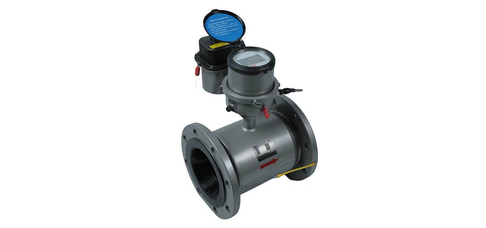
For a conventional full-pipe electromagnetic meter, confirm that the measuring tube will remain filled during operation. A location that can drain or retain air may affect measurement even when the selected flow range appears suitable.Check the water’s conductivity against the proposed model’s requirements. Also review the electrical reference and grounding arrangement for the actual pipe material, lining and meter design. These details belong in the installation review, particularly where plastic or internally lined pipework is involved.Obtain the manufacturer’s requirements for mounting orientation, straight pipe lengths and nearby valves or bends. Have the supplier review the proposed pipe arrangement against those installation requirements.
Ask electromagnetic water meter manufacturers to connect their recommendation to the supplied flow profile. The technical submission should identify the model, flow-range configuration, installation requirements and pressure-loss information relevant to the proposed duty.For an electromagnetic water flow meter used in a utility project, request applicable test documentation and approval details for the ordered configuration. Record any conditions attached to those documents.At commissioning, retain the meter identity, installation checks, initial totalizer reading and results from the agreed verification procedure. A selection record linked to the installed meter makes later investigations easier to follow.
Use the flow profile to shortlist suitable measuring ranges, then review connections and hydraulic conditions. An alternative diameter may require pipework changes and a pressure-loss assessment before it can be accepted.
Q1 identifies the minimum rated flow for operation within the applicable error limits. Q3 identifies the permanent-flow rating. Both are needed to assess the proposed operating range.
R250 describes the ratio Q3/Q1. It does not specify one error percentage. Review the declared accuracy class, flow zone, operating conditions and supporting documentation for the proposed meter.
Do not assume that it will. Q1 establishes a boundary for rated metrological performance. Ask for evidence of expected behaviour at the site’s minimum flow.
Supply minimum, typical and peak flows, peak duration, pipe details, water conditions, available pressure and the installation layout. Include communication requirements and any project-specific acceptance criteria.
A suitable electromagnetic water meter matches the site’s operating flows and installation conditions. Checking Q1 and Q3 together exposes mismatches between peak capacity and minimum-flow requirements.For a project discussion with Sanchuan, prepare the flow profile, existing pipe details and proposed installation arrangement. Confirm the specified configuration against site conditions before placing the order.